MonoGame (new XNA) Tutorial:
Platformer Game Programming Tutorial
With Effects and Smooth Animation
(Page1, Page2, Page3, Page4, Page5)
Page5:
Introduction to Shaders (skip ahead a bit if already familiar):
Vertex shaders make changes to the vertices of the primitives to be rendered. This can be useful if you wanted to over-ride the regular vertex shader to make one that provides swaying or waving motions to the vertices in the scene (like a tree made of multiple vertices that you want to sway)... Could also be useful in making wobbly effects or other interesting distortions. We would normally always apply a WorldTransformation matrix to the vertices so they're moved into the correct positions for proper viewing (this is already done in the default vertex shader for spriteBatch and the one we made for QuadEffect.fx for quadBatch). Color information can also be applied or modified to vertices. Potentially if working in 3D, normals can also be processed or modified at each vertex. Normals are the vector directions that point away from the surfaces - however for a vertex a normal is the average direction of all neighboring faces - this is useful for lighting calculations. For our purposes, we setup a vertex declaration for processing only: position, color, texture_coordinate
We'll also use an output format of position, color and tex_coord... and must ensure the pixel shader receives the exact same format as used in the output from the vertex shader.
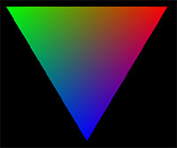
Note that the color values are interpolated between vertices... so the color value passed into the pixel shader will be a bit different for each pixel if the vertex colors aren't the same. So as it scans the vertices the color slowly changes to the other vertex value as it gets closer to it while processing pixels. Example(without texture):
Pixel shaders (called Fragment shaders in GLSL) work on individual pixels. All the pixels are represented as values ranging from (0.0 to 1.0) across and (0.0 to 1.0) down. So with a resolution of 800x600 for example, the pixel at 400, 300 would be (0.5, 0.5) since it's halfway across width and halfway across height.
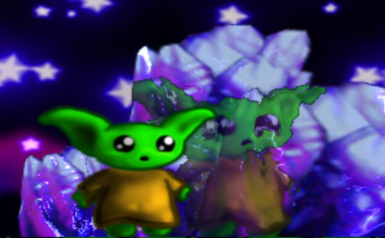
For example, to get the width and height of a single pixel, you'd need to calculate it as: new Vector2( 1.0f/display_width, 1.0f/display_height ); and then pass it into the shader using SetValue and receive it as a global float2 in the fx file (which is just like HLSL). You could use pixel shaders, for example, to create heat haze, underwater effects, specular bump/normal mapping (make detailed surface lighting), various lighting fx, color correction, or in the case of this tutorial, we'll use it to make distorted reflections with shimmer. Example below is use of our crystal shader we're going to make:
Geometry shaders also exist which come before pixel shading.
They can for example, add(or remove) vertices to smoothen surfaces - this is for advanced 3D stuff. We won't be using this but I thought I'd mention it anyway.
Note: OpenGL uses something called GLSL and for DirectX it is HLSL. The
fx file is virtually the same as HLSL and allows multiple shaders which can be dispatched to use based on what is needed. (I'm not a shader expert so I'm not sure of what other differences there may be). In GLSL you can pass values into what's called a uniform (and use "in" and "out" to determine what's passed between vertex and pixel shaders) where in HLSL it's typically passed into a packed constant buffer (up to 4 floats for each cbuffer and use padding [ie: float padding] for any remaining part of it unused). In our fx file we'll simply state our globals and the compiler will take care of the rest. Values are passed in from c# using for example: shader.Parameters["timing"].SetValue(current_time);
!!!Important Notes!!!
When creating shaders, you may include values that aren't currently being used for the end result. Whenever this happens, the compiler will remove the unused portions... This means trying to pass something into an unused parameter will fail causing null exception or some other error. Ensure that everything in your final shader to compile is being used (especially if trying to pass parameter values to something that might not be used). Also make sure to pass your textures using SetValue. ie: shader.Parameters[TexSamp].SetValue(myTexture); Something like: device.Textures[2] = some_tex; probably won't work. (should work for 0 if done right before device.DrawUserIndexedPrimitives)...
Samplers:
For each texture you need to use with your shader, you need a sampler (can think of this as your texture if you like). For each one, you provide a name (like TexSamp) and assign a register in order starting with s0 for the first one. ie: s0, s1, s2, s3.... (not sure how many) [sampler is like SamplerState in HLSL)
sampler TexSamp : register(s0)
{ };
Optional settings:
Filters:
Filter is regular smoothing strategy, but there's also MinFilter, MagFilter (for scaling), and
MipFilter (if using Mip mapping for LOD)
We'll only be using Filter.
Point (lower quality [no smoothing] - good for retro style games
Linear
- ( most common for our purposes ) - good performance and smoother look
Anisotropic - less performance but smooth high quality looking result
AddressU, AddressV:
(this tells it what to do when the sampling source[u,v coords] goes over the edges of the texture)
Clamp - just keep using the last color used at the edge of the texture
Wrap - wrap around to the other side of the texture and keep sampling (good for scrolling or repeating tiles [like for landscapes])
Mirror - start sampling in the other direction after reaching the edge (I like this one for water effects [also good for repeating])
(I believe you can set as Border and some BorderColor also if needed)
-------------------------
71) Start a new Shader file and rename it: Crystal.fx and put it in your Content folder, adding it also with the Monogame Pipeline.
a) Begin by adding our 3 texture sources to sample from:
- sampler TexSamp : register(s0)// what is being drawn
- {
- Filter = Linear;
- AddressU = Clamp;
- AddressV = Clamp;
- };
- sampler ReflectSamp : register(s1) // sprites to reflect
- {
- Texture = (ReflectMap);
- Filter = Linear;
- AddressU = Clamp;
- AddressV = Clamp;
- };
- sampler BackSamp : register(s2) // background to refract
- {
- Texture = (BackMap);
- Filter = Linear;
- AddressU = Wrap;
- AddressV = Wrap;
- };
Optionally, I put Filters to Linear (which it would be doing anyway by default based on device state set in Begin)
but you could play with these if you wanted.
For the image being drawn (texture containing crystals themselves), and the sprites to reflect (from sprite target), I set it to Clamp to the edge of the texture if sampling outside of it... this will NEVER happen in this case - I only included these optional parameters as a means of showing examples.
For the BackSamp (background image used to make refractive shimmering), I set it to Wrap because it may actually need to when sampling (ie: if we used a wrapping background smaller than the display resolution)
b) We'll need the screen(target-display) dimensions so we'll pass that value into screen (only need to do once - not each loop).
- float2 screen;
- static const float scale= 0.79; // 0.1 = big, 0.9 = small (1-0 instead of 0-1 because of extraction method)
- static const float distort_amount = 0.007; // maybe 0.001 to 0.04
- static const float visibility = 0.7;// visibility of reflection
- screen (x,y) = width, height
- scale is the opposite of how scale normally works (ie: 0.1 would be huge and 0.9 would be small) ... this changes the size of the sprites reflected on the crystals [it's opposite because of extraction method - you'll see]
- visibility = transparency of reflection
c) The Pixel Shader function...
Rem: must take exact same parameters as vertex shader used in its output (ie: see the default fx file's vertex shader)
tiles_image is where TexSamp will be sampling from since that's where the crystals are located.
If you look at the image, you'll notice I put a normal map on it that is precisely 128 pixels to the right of it. The normal-map will be used to create the distorted reflections and sort-of specular-shimmer effect.
- //--------------------------------------
- // C R Y S T A L P I X E L S H A D E R
- //--------------------------------------
- float4 CrystalPS(float4 pos : SV_Position, float4 col : COLOR0, float2 uv : TEXCOORD0) : COLOR0
- {
- float2 norm_uv = uv;
- norm_uv.x+=0.125; // 128 pixels to right on tiles_image (which has 1024 total width) so 128/1024 = 0.125
- float2 reflect_uv;
- reflect_uv.x = pos.x/screen.x*scale+0.05;
- reflect_uv.y = pos.y/screen.y*scale+0.10;
- // r=0-1, g=0-1 and say red = 0.4 and green = 0.7 then distort.x = -0.2 and distort.y = 0.4 (ranging -1 to +1) This is why: *2 - 1
- // multiply final result by magnitude to get it in terms of a small space of distortion in screen/uv coords (0-1)
- float2 distort = (tex2D(TexSamp, norm_uv).xy*2.0-1.0)*distort_amount; // norm_uv = uv_coords on the tiles sheet for normal map
- float4 TexColor = tex2D(TexSamp, uv); // color of pixel to draw from crystals
- reflect_uv.xy += distort.xy;
- float4 sparkle = tex2D(BackSamp, (reflect_uv + distort*6));
- if (TexColor.a>0.5) TexColor+=sparkle;
- float4 Reflect = tex2D(ReflectSamp, reflect_uv); // alien hero pixel to reflect
- if ((TexColor.a>0.5)&&(Reflect.a>0.9)) {TexColor = Reflect*visibility + ((TexColor+sparkle)*(1-visibility));}
- return TexColor*col;
- }
As you may already know the normals along the surface of the normal map sort of determine the angle the surface would face at where the red areas would take on more light (from upper-right side in this case) and the green areas would be more shadowed(bottom-left sides of each bump).
- norm_uv is set to 128 pixels to the right (128/map_width) = 0.125 (now set for values ranging 0-1 which are valid in the shader)
- reflect_uv = (position / screen_dimension) [to get 0-1 of position] * scale
You may notice that
scaling a value, ie: 0.3 * 2 = 0.6... but that would expand the uv sampling (skipping pixels) and thus it would shrunk the image... we want to make it bigger so we set our scale smaller so that it samples pixels closer together (maybe the same one twice sometimes) to make the image bigger.
I added 0.05(X) and 0.10(Y) values to offset the sampling position a bit so that the reflection won't appear directly under the character (if you wanted you could even make this parametric so that as the character walks by the surface, the angle of reflection appears to change)
This line:
float2 distort = (tex2D(TexSamp, norm_uv).xy*2.0-1.0)*distort_amount; // norm_uv = uv_coords on the tiles sheet for normal map
... gets the Red and Green values from the normal map (xy) and adjusts their values to range (-1 to +1) [this is why we go *2-1]
Once we have the red,green values going (-1 to 1, -1 to 1) we multiply this by how much distortion we want using values ranging from (0.001 to 0.04) ... so if for example the red were 0.4 (with distort amount of 0.007), it would become first (0.8-1 = -0.2) and then * 0.007 = -0.014 ... this will be used as a tiny offset to the uv coordinate to create a bit of distortion based on the normal-map surface:
reflect_uv.xy += distort.xy;
Now when we get the reflection color (Reflect = tex2D(ReflectSampl, reflect_uv) ... it will get a distorted version of the sprites or alien character using the normal-map distorted uv coord.
sparkle = tex2D(BackSamp, (reflect_uv+distort*6)); This also extracts in a distorted way but from a background image (or whatever you want to create the shimmer with) and by adding 0.042 to u and v it will extract it in a different way -- you can experiment with the distortion value here to get a more favorable look to the shimmer/sparkle.
The line:
if (TexColor.a>0.5) TexColor+=sparkle;
This makes it so only fairly solid colors on the crystal will have sparkles added to them. It wouldn't make sense if completely transparent parts of the image rectangle had sparkles on them too - otherwise you'd have a sparkling rectangle over each crystal.
The line:
if ((TexColor.a>0.5)&&(Reflect.a>0.9)) {TexColor = Reflect*visibility + ((TexColor+sparkle)*(1-visibility));}
IF this pixel is on the actual crystal AND the reflection pixel is solid (ie: avoid edges or transparency), THEN:
Crystal color =
Reflect color(distorted sprites) * visibility +
(Crystal color + distorted-sparkle-color)
* inverse visibility
In other words, if reflection should be more visible then crystal+sparkle should be less visible and it will ignore shading for pixels that are see-through just using the original TexColor (crystal color)
---------------------------
d) Make sure you've saved and added this Crystal.fx to your Content.
Now go back into game1.cs and if you don't already have all of this - make sure to add them:
add to your variables (maybe somewhere after RenderTargets):
- //FX
- Effect crystal_fx; // reflective crystal effect
In LoadContent(), after map.SetTilesImage (before sheet_mgr.Setup_Sheet_Level_1):
- // FX
- crystal_fx = Content.Load<Effect>("Crystal");
- crystal_fx.Parameters["screen"].SetValue(new Vector2(screenW,screenH)); // screen(target) resolution
- crystal_fx.Parameters["BackMap"].SetValue(far_background); // image to make shimmer from
- set the float2 screen value in the shader to the target display dimensions
- set the value for the far_background (point to this part of the video ram for the BackMap sampler)
[you could use another texture source too for sparkle or shimmer effect]
If you didn't add this already:
- // APPLY A CRYSTAL EFFECT TO THESE:
- crystal_fx.Parameters["ReflectMap"].SetValue(sprite_target);
- spriteBatch.Begin(SpriteSortMode.Deferred, BlendState.AlphaBlend, SamplerState.LinearClamp, DepthStencilState.None, RasterizerState.CullNone, crystal_fx);
- map.DrawCrystals(); // D R A W C R Y S T A L S
- spriteBatch.End();
Need to pass the new sprite_target into ReflectMap each frame (since it keeps changing)
Note: the Begin includes adding the crystal_fx (so it will bypass the default pixel shader for now)
map.DrawCrystals now draws them with the cool sparkling distortion effect...
(Note: end will return us to using default shaders again)
Hopefully I didn't miss anything. Review the source code to see if anything's missing (like in Game1.cs for example):
>>> SOURCE CODE <<<
NOTE: Updated rutime cs code for MeoMotion 2018/2019 code adds support for color interpolation and Additive Blendstate and can be downloaded here. >>new MeoMotion classes<<